Project Overview
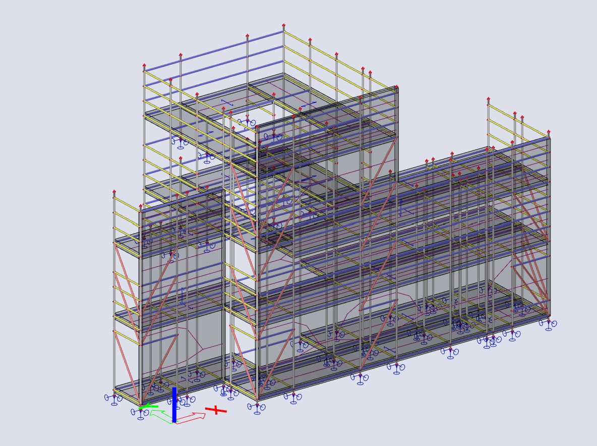
AR-TEC carried out the complete structural assessment of a complex modular façade scaffold at Plateellaan in Rijnsburg. The scaffold contains multiple working levels, changes in height, projecting platforms, internal openings and interconnected sections surrounding the existing structure.
One of the most important requirements of this project was that the scaffold could not be anchored to the building. The complete arrangement therefore had to function as an independent, free-standing temporary structure.
An unanchored scaffold behaves differently from a conventional tied façade scaffold. Building anchors normally transfer horizontal wind forces and restrict lateral movement. Without these anchors, the scaffold itself must provide sufficient stiffness, strength and resistance against sway, overturning and instability.
The stability of this structure was achieved through its interconnected three-dimensional arrangement, adequate base width, continuous ledgers and transoms, strategically positioned diagonal bracing and effective interaction between the different scaffold elevations.
The returns, corners and interconnected scaffold sections were important to the overall structural behaviour. Together, they allowed horizontal forces to be distributed across a wider part of the structure instead of being resisted by a single façade line.
The scaffold reached a maximum height of approximately 9.0 m, with a maximum bay size of 2.57 × 1.40 m and a maximum lift height of 2.50 m. These dimensions were included directly in the structural model.
A detailed three-dimensional model was developed using the dedicated scaffolding module in SCIA Engineer. The model included standards, ledgers, transoms, guardrail members, platforms, diagonal braces, base plates and adjustable base jacks.
The mechanical properties of the modular scaffold components were assigned using the applicable system and supplier information. Standard scaffold tubes were represented using Ø48.3 × 3.2 mm steel sections, together with the relevant cross-sectional and material properties.
The connection behaviour of the modular ring system was included through appropriate spring and rotational stiffness values. This was important because scaffold connections are not fully rigid and should not be modelled in the same way as welded connections in a permanent steel structure.
The model also considered the difference between the calculated weight of plain scaffold tubes and the actual weight of the complete modular system, including rings, wedge heads and couplers. A factor of 1.24 was applied to represent the system self-weight more accurately.
The construction lift shown within the overall arrangement was treated as an independent structure and was not anchored to the scaffold. This prevented unsupported lift forces from being transferred into the temporary scaffold model.
The scaffold was not provided with wind-reducing mesh. The wind assessment therefore considered the actual exposed area of the open scaffold components and the influence of the adjacent building.
The applied loading included scaffold self-weight, platform and floor-component weight, working-platform loading and wind actions. A working load of 3.00 kN/m² was included in the SCIA Engineer model.
Both working wind and maximum wind conditions were considered. The basic peak pressure values used in the assessment were 0.21 kN/m² for working wind and 0.70 kN/m² for maximum wind.
Wind pressure and suction were evaluated in the required directions. The exposed scaffold area, force coefficient and influence of the building façade were included when determining the wind loads applied to the model.
Separate load combinations were developed for serviceability, member strength and overall stability. Maximum wind was combined with a reduced portion of the working load, while working wind was assessed together with the full operational loading where required.
A second-order, geometrically nonlinear analysis was performed in SCIA Engineer. This method accounts for changes in structural geometry as the scaffold deforms under load.
The nonlinear method was especially important because the scaffold was unanchored. It allowed AR-TEC to evaluate additional P-Delta effects, stiffness reduction, redistribution of forces and the possibility of global instability.
The analysis checked whether the complete scaffold could reach equilibrium under the governing load combinations without relying on lateral support from the existing building.
Standards were checked for axial compression, bending moments, combined interaction and buckling. Their effective lengths and restraint conditions were determined from the actual arrangement of ledgers, transoms and diagonal braces.
Ledgers and transoms were assessed for axial force, bending, shear and their contribution to the horizontal stiffness of the scaffold.
Diagonal braces were evaluated for tension and compression forces. Their positions were reviewed to ensure that the different scaffold sections had a continuous lateral load path in both principal directions.
The complex transitions between lower platforms, upper working levels and projecting scaffold sections were checked carefully. These locations can attract concentrated forces because the geometry and stiffness of the structure change.
The platform load distribution was reviewed to confirm that working loads were correctly transferred through the decks and transoms into the standards and finally to the supporting ground.
Overall displacement and sway were examined under working wind and maximum wind conditions. Controlling horizontal movement was essential because no building anchors were available to restrain the scaffold.
Global stability combinations were evaluated using reduced stabilising permanent loads together with amplified wind actions. This provided a conservative check against loss of stability under the most critical wind condition.
The reactions at all base-jack locations were extracted from the SCIA model. These reactions were used to understand how the scaffold loads were distributed over the supporting surface.
The maximum characteristic standard reaction was calculated as 9.38 kN, while the maximum design reaction, including the applicable safety factors, was 13.32 kN.
These reactions provide the required design information for checking the capacity of the ground, supporting slabs, sole boards or other bearing arrangements beneath the scaffold.
The governing member utilisation ratio obtained from the completed analysis was 0.63, which remained below the allowable limit of 1.00.
The final calculation therefore demonstrated that the scaffold satisfied the specified requirements for strength, stiffness and stability under the adopted design assumptions.
The successful verification of this project was not based simply on removing anchors from a conventional scaffold. The entire scaffold geometry, footprint, connection behaviour and bracing arrangement were analysed as a complete free-standing structural system.
This project demonstrates AR-TEC’s capability to engineer complex temporary structures where conventional building anchors cannot be used. Through realistic modelling and nonlinear analysis, the scaffold was verified to remain structurally stable without relying on support from the existing building.
APPLICABLE DESIGN STANDARDS
NEN-EN 12810 – Façade Scaffolds Made of Prefabricated Components
NEN-EN 12811 – Temporary Works Equipment and Scaffolds
NEN-EN 12812 – Falsework and Supporting Structures
NEN-EN 12813 – Prefabricated Load-Bearing Towers
NEN-EN 1991-1-1 – Permanent and Imposed Loads
NEN-EN 1991-1-4 – Wind Actions
NEN-EN 1993-1-1 – Steel Structure Design
NEN-EN 1993-1-8 – Steel Connection Design


 Completed